
Circuit Breaker Symbol Single Line Diagram
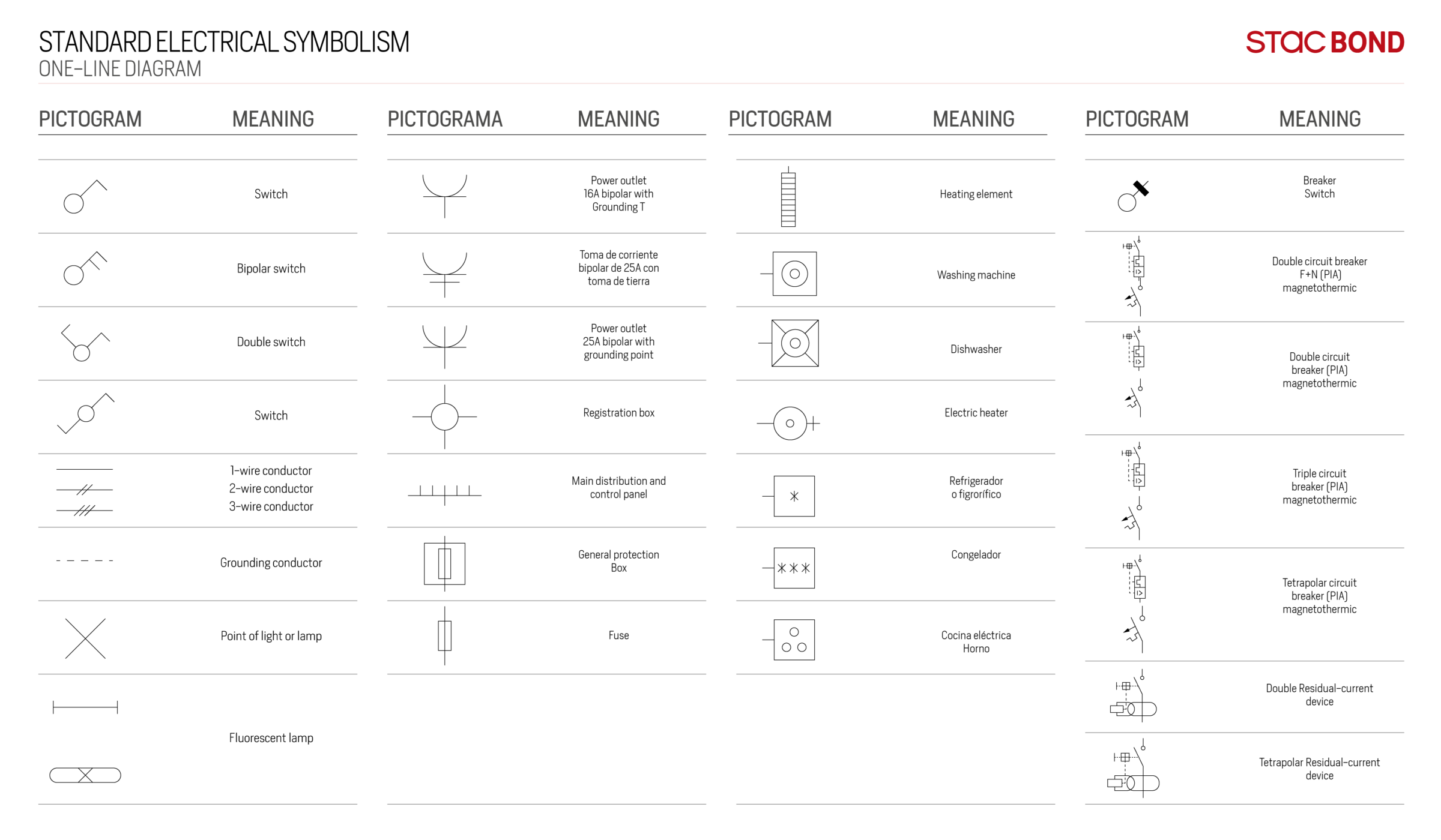
One-line diagram - a diagram that uses single lines and graphic symbols to indicate the path and components of an electrical circuit. One-line diagrams are used when information about a circuit is required but detail of the actual wire connections and operation of the circuit are not. Line Diagrams

Circuit Breaker Symbol Single Line Diagram Learn To Interpret Single
Basics 3 4.16 kV Bus 1-Line : Basics 4 600 V 1-Line : Basics 5 480 V MCC 1-Line : Basics 6 7.2 kV 3-Line Diagram : Basics 7 4.16 kV 3-Line Diagram : Basics 8 AOV Elementary & Block Diagram : Basics 9 4.16 kV Pump Schematic : Basics 10 480 V Pump Schematic : Basics 11 MOV Schematic (with Block included) Basics 12 12-/208 VAC Panel Diagram
Oneline Diagrams Solution
These loads are connected by cables or busbars which must be clearly shown in the single-line diagram. Also, a single-line diagram represents comprehensive data for each component or device connected to it. In other words, the exact cable sizes, circuit breakers ratings, voltage drop values, and short circuit current calculated values must be.

Circuit Breaker Switch Schematic Symbol Single Line Circuit Diagram
Relays form switches in your electrical circuit. In Lucidchart, there are four major types of relay symbols that are labeled. They include both the full name, e.g. Single Pole Single Throw, and its abbreviation—in this case, SPST. You can easily rotate a relay, or any other icon in Lucidchart, to fit the parameters of your circuit diagram.
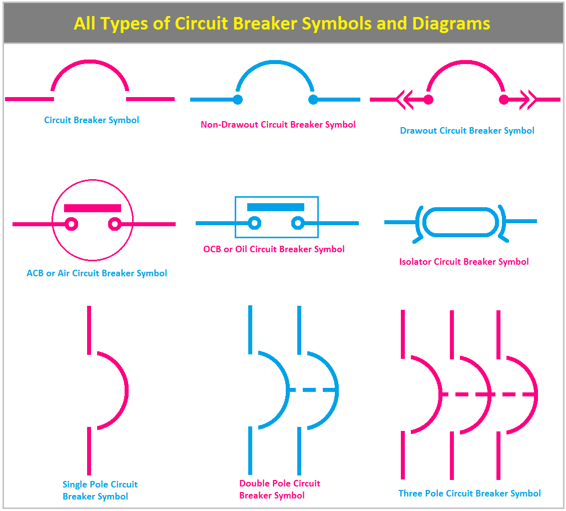
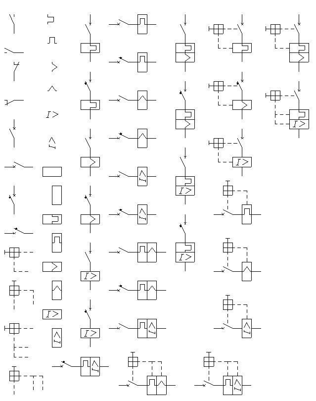
All Types of Circuit Breaker Symbols and Diagrams ETechnoG
Initially, the Single Line Diagram (SLD) provides a framework for the incorporation of different types of required information such as: Incoming service voltage and utilization voltages required. Electrical distribution equipment ampacity and short-circuit ratings. Overcurrent / short-circuit protection.
Electrical One Line Diagram Symbols
In power engineering, a single-line diagram ( SLD ), also sometimes called one-line diagram, is a simplest symbolic representation of an electric power system.

Singleline diagram of one breaker and a half configuration. Download
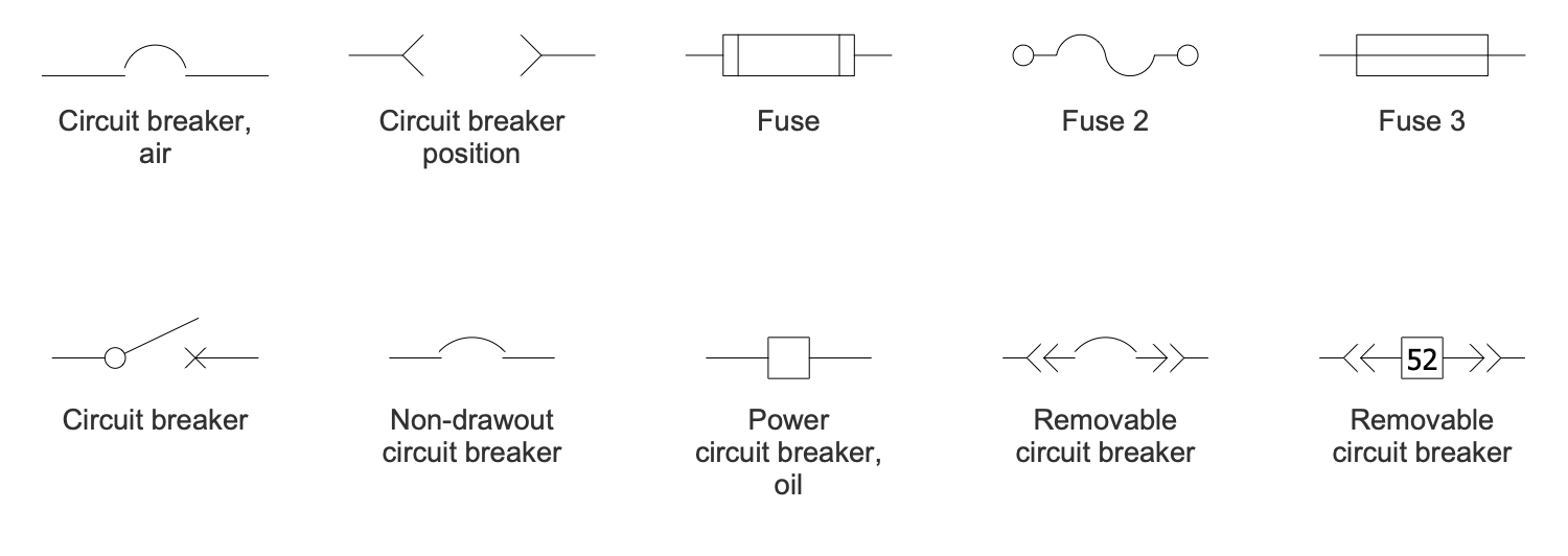
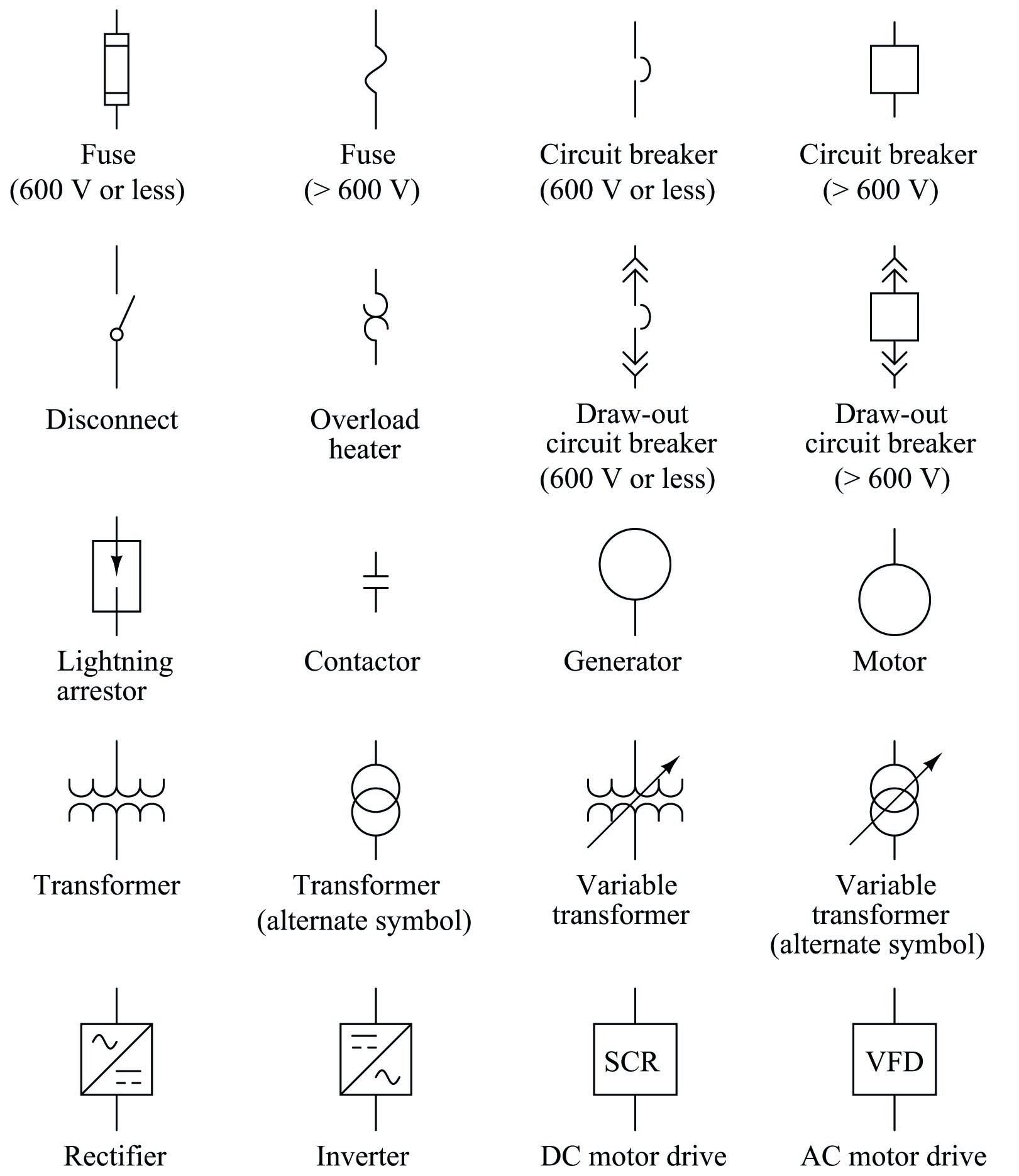
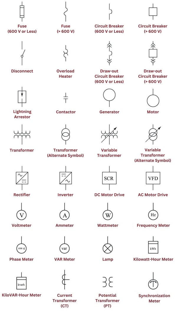
A one-line diagram is an important means The one-line diagram symbols presented here are of communicating the components, electrical commonly accepted symbols. Individual symbols relationships, and connections within a circuit or with an identification and brief explanation and/or system.
Singleline Electrical Diagrams Electric Power Measurement and
It is the symbol for fuse switch disconnector. It is a fuse in series with a switch. It can switch the device manually and also provide the protection against overcurrent by breaking the circuit. Protection Resistor These both symbols represent a protection resistor.
Circuit Breaker Symbol Single Line Diagram
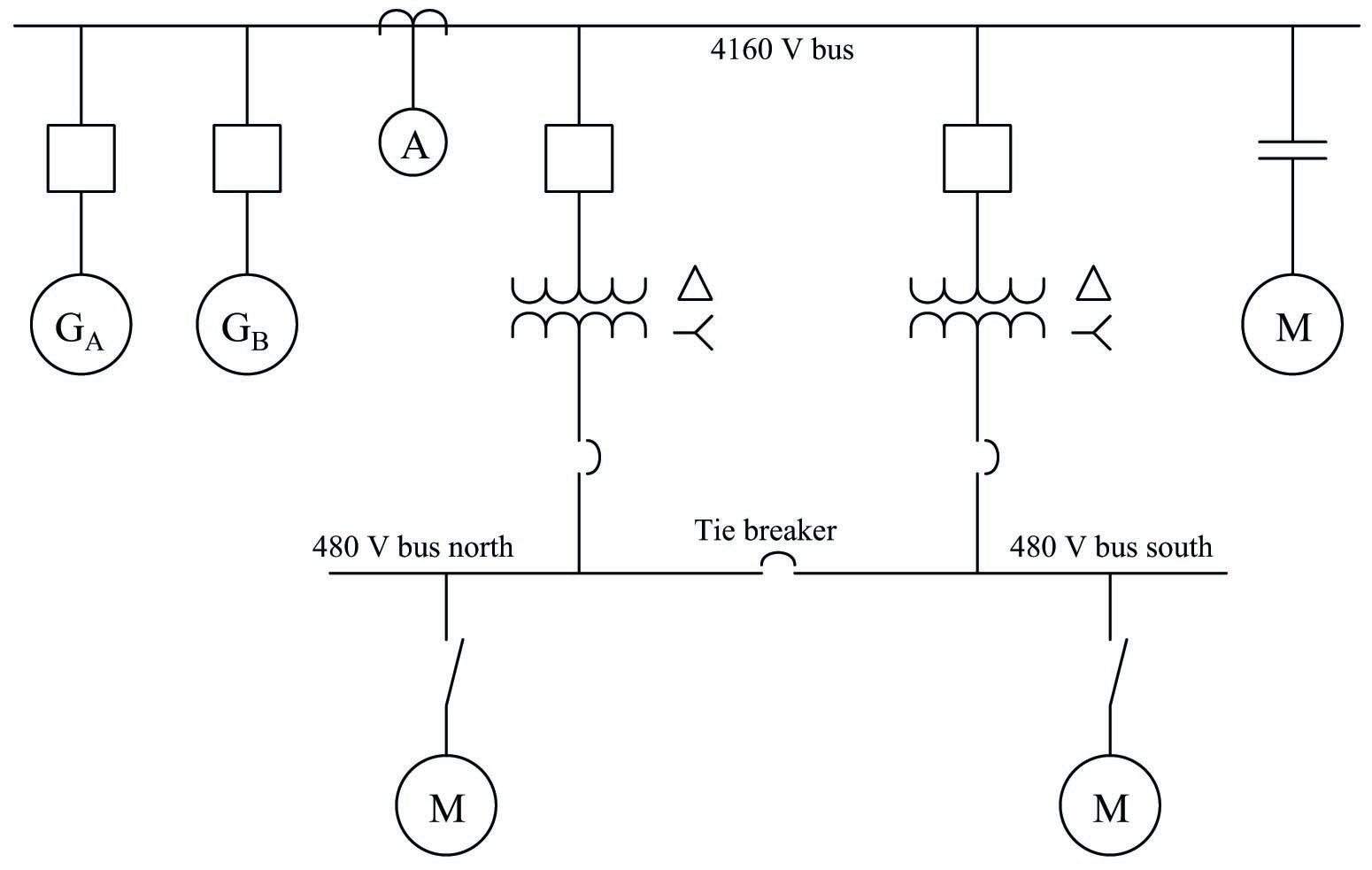
When interpreting a single line diagram, you should always start at the top where the highest voltage is and work your way down to the lowest voltage. This helps to keep the voltages and their paths straight. To explain this easier, we have divided the single line into three sections.
Singleline diagram How to represent the electrical installation of a
A single line can show all or part of a system. It is very versatile and comprehensive because it can depict very simple DC circuits, or a very complicated three-phase system. Learn To Interpret Single Line Diagram - SLD (on photo: An example of 66/6.6kV power substation single line diagram)

Circuit Breaker Symbol Single Line Diagram / CIRCUIT DIAGRAM SYMBOLS
The last piece of electrical equipment in the middle portion of the diagram is another circuit breaker (b3). This time, however, the circuit breaker is a fixed low voltage circuit breaker, as indicated by the symbol. Moving to the bottom area of the single line diagram, notice that the circuit breaker (b3) in the middle is

Circuit Breaker Electronic Symbol Electrical Network Schematic
Draftman. Electrical single-line diagrams and schematic symbols are essential tools in electrical engineering and circuit design. They are used to represent and communicate the structure and connections within an electrical system in a simplified and standardized manner.
wiring a single pole breaker
Circuit Breaker 3P Single Line Symbols. Back to symbols. Sample Drawings. JIC / NFPA Sample Drawing; IEC 60617 Sample Drawing; P&ID PIP Sample Drawing; Hydraulic Sample Drawing; Pneumatic Sample Drawing; Stencils. ABB; AC500 PLC COMM INT Modules; AC500 PLC COMM INT Modules - Layout;

Circuit Breaker Symbol Single Line Diagram
Single line symbols electrical symbols used to represent various electrical devices for usages in electrical schematic design. Circuit Breaker 3P - Thermal. Reference: Q1. Component: MCB 3P. Category: Circuit Breakers. Stencil: Single Line Symbols. Tags: circuit breakers, thermal. Edit.

Circuit Breaker Symbol Single Line Diagram / CIRCUIT DIAGRAM SYMBOLS
The Single-Line Diagram (SLD) is a fundamental representation of an electrical system, providing a simplified view of its components, interconnections, and electrical flow paths. It is a one-line drawing that depicts the power distribution and control circuits clearly and concisely. Before moving further, have a quick look at the following.

Single Line Diagram Circuit Breaker Symbol
In a single-line electrical diagram, each transmission or distribution power line appears as a single line on the page, rather than as three (or four) lines showing individual conductors in a three-phase AC circuit. This condenses the space and complexity of the diagram for simpler troubleshooting.
